
路由交换综合5 实验报告
日期:2023年12月12日
目录
1、网络规划设计 1
实验网络拓扑图 1
实验硬件设备需求表 1
实验ip规划表 2
2、路由规划 3
3、site 1 区域基础网络配置 4
4、site 2 区域基础网络配置 12
5、 骨干区域基础网络配置 14
6、site 1 mpls vpn配置 22
7、site 2 mpls vpn配置 24
8、骨干区域 mpls vpn配置 25
9、 业务测试 32
10、 切换测试 32
1、网络规划设计
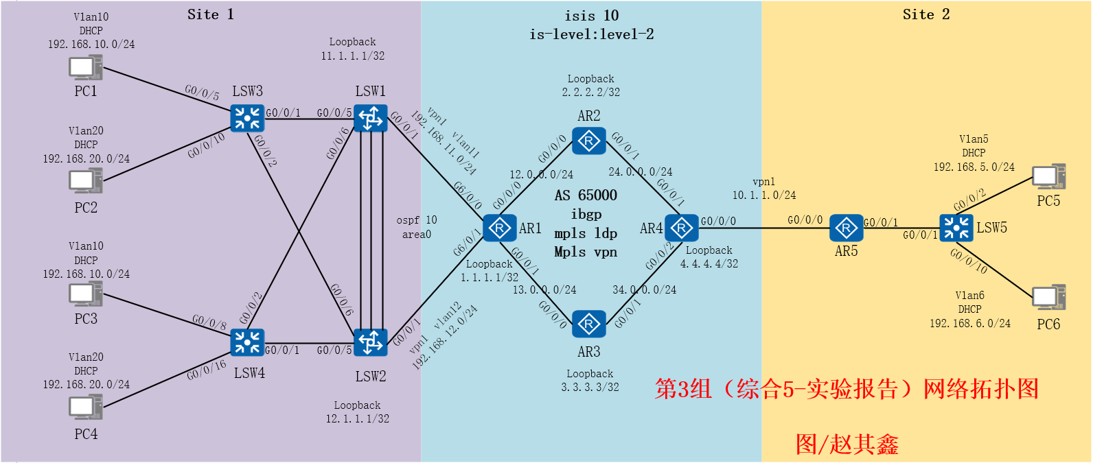
实验网络拓扑图
实验硬件设备需求表
| 硬件类型 | 产品名称 | 数量 |
| 路由器 | 华为 AR2200 Series | 5 |
| 交换机 | 华为 Quidway S5700 | 2 |
| 交换机 | 华为 Quidway S3700 | 3 |
| 终端设备PC | 宏碁 Veriton D630 | 6 |
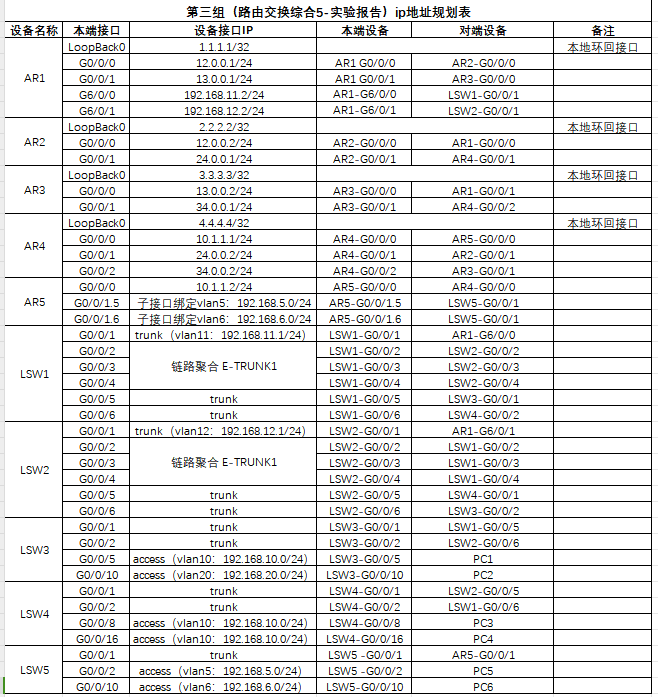
实验ip规划表
2、路由规划
LSW1:
VLAN10:192.168.10.0/24
VLAN20:192.168.20.0/24
VLAN11:192.168.11.0/24
Loopback 0:11.1.1.1/32
使用路由协议:VRRP,OSPF,MSTP
LSW2:
VLAN10:192.168.10.0/24
VLAN20:192.168.20.0/24
VLAN11:192.168.12.0/24
Loopback 0:12.1.1.1/32
使用路由协议:VRRP,OSPF,MSTP
AR1:
GE0/0/0:12.0.0.0/24
GE0/0/1:13.0.0.0/24
GE6/0/0:192.168.11.0/24
GE6/0/1:192.168.12.0/24
Loopback 0 :1.1.1.1/32
使用路由协议:BGP,OSPF,ISIS,MPLS
AR2:
GE0/0/0:12.0.0..0/24
GE0/0/1:24.0.0.0/24
Loopback 0 :2.2.2.2/32
使用路由协议:BGP,OSPF,ISIS,MPLS
AR3:
GE0/0/0:13.0.0.0/24
GE0/0/1:34.0.0.0/24
Loopback 0 :3.3.3.3/32
使用路由协议:BGP,OSPF,ISIS,MPLS
AR4:
GE0/0/0:10.1.1.0/24
GE0/0/1:24.0.0.0/24
GE0/0/2:34.0.0.0/24
Loopback 0 :4.4.4.4/32
使用路由协议:BGP,OSPF,ISIS,MPLS
AR5:
GE0/0/0:
GE0/0/1:
Loopback 0 :
使用路由协议:BGP,OSPF,ISIS,DHCP
3、site 1 区域基础网络配置
LSW3:
sysname LSW3
#
vlan batch 10 20
#
interface GigabitEthernet0/0/1
port link-type trunk
port trunk allow-pass vlan 2 to 4094
#
interface GigabitEthernet0/0/2
port link-type trunk
port trunk allow-pass vlan 2 to 4094
#
interface GigabitEthernet0/0/5
port link-type access
port default vlan 10
#
interface GigabitEthernet0/0/10
port link-type access
port default vlan 20
#
LSW4:
sysname Lsw4
#
vlan batch 10 20
#
interface GigabitEthernet0/0/1
port link-type trunk
port trunk allow-pass vlan 2 to 4094
#
interface GigabitEthernet0/0/2
port link-type trunk
port trunk allow-pass vlan 2 to 4094
#
interface GigabitEthernet0/0/8
port link-type access
port default vlan 10
#
interface GigabitEthernet0/0/16
port link-type access
port default vlan 20
#
LSW1:
sysname LSW1
#
vlan batch 10 to 11 20
#
stp instance 1 priority 4096
stp instance 2 priority 8192
#
dhcp enable
#
stp region-configuration
region-name huawei
instance 1 vlan 10
instance 2 vlan 20
active region-configuration
#
bfd
#
interface Vlanif10
ip address 192.168.10.253 255.255.255.0
vrrp vrid 10 virtual-ip 192.168.10.254
vrrp vrid 10 priority 150
vrrp vrid 10 track bfd-session session-name 1 reduced 30
dhcp select interface
dhcp server excluded-ip-address 192.168.10.248 192.168.10.252
#
interface Vlanif11
ip address 192.168.11.1 255.255.255.0
#
interface Vlanif20
ip address 192.168.20.254 255.255.255.0
vrrp vrid 20 virtual-ip 192.168.20.254
dhcp select interface
dhcp server excluded-ip-address 192.168.20.249 192.168.20.253
#
interface Eth-Trunk1
port link-type trunk
port trunk allow-pass vlan 2 to 4094
mode lacp-static
max active-linknumber 2
#
interface GigabitEthernet0/0/1
port link-type access
port default vlan 11
#
interface GigabitEthernet0/0/2
eth-trunk 1
#
interface GigabitEthernet0/0/3
eth-trunk 1
#
interface GigabitEthernet0/0/4
eth-trunk 1
#
interface GigabitEthernet0/0/5
port link-type trunk
port trunk allow-pass vlan 2 to 4094
#
interface GigabitEthernet0/0/6
port link-type trunk
port trunk allow-pass vlan 2 to 4094
#
interface LoopBack0
ip address 11.1.1.1 255.255.255.255
#
bfd 1 bind peer-ip 192.168.11.2 interface Vlanif11 source-ip 192.168.11.1 auto
commit
#
ospf 10
area 0.0.0.0
network 192.168.10.0 0.0.0.255
network 192.168.20.0 0.0.0.255
network 192.168.11.1 0.0.0.0
#
LSW2:
sysname LSW2
#
vlan batch 10 12 20
#
stp instance 1 priority 8192
stp instance 2 priority 4096
#
dhcp enable
#
stp region-configuration
region-name huawei
instance 1 vlan 10
instance 2 vlan 20
active region-configuration
#
bfd
#
interface Vlanif10
ip address 192.168.10.254 255.255.255.0
vrrp vrid 10 virtual-ip 192.168.10.254
dhcp select interface
dhcp server excluded-ip-address 192.168.10.249 192.168.10.253
#
interface Vlanif12
ip address 192.168.12.1 255.255.255.0
#
interface Vlanif20
ip address 192.168.20.253 255.255.255.0
vrrp vrid 20 virtual-ip 192.168.20.254
vrrp vrid 20 priority 150
vrrp vrid 20 track bfd-session session-name 2 reduced 30
dhcp select interface
dhcp server excluded-ip-address 192.168.20.248 192.168.20.252
#
interface Eth-Trunk1
port link-type trunk
port trunk allow-pass vlan 2 to 4094
mode lacp-static
max active-linknumber 2
#
interface GigabitEthernet0/0/1
port link-type access
port default vlan 12
#
interface GigabitEthernet0/0/2
eth-trunk 1
#
interface GigabitEthernet0/0/3
eth-trunk 1
#
interface GigabitEthernet0/0/4
eth-trunk 1
#
interface GigabitEthernet0/0/5
port link-type trunk
port trunk allow-pass vlan 2 to 4094
#
interface GigabitEthernet0/0/6
port link-type trunk
port trunk allow-pass vlan 2 to 4094
#
interface LoopBack0
ip address 12.1.1.1 255.255.255.255
#
bfd 2 bind peer-ip 192.168.12.2 interface Vlanif12 source-ip 192.168.12.1 auto
commit
#
ospf 10
area 0.0.0.0
network 192.168.10.0 0.0.0.255
network 192.168.20.0 0.0.0.255
network 192.168.12.1 0.0.0.0
#
4、site 2 区域基础网络配置
[AR5]
sysname AR5
dhcp enable
acl number 3000
rule 5 deny ip source 192.168.6.0 0.0.0.255 destination 192.168.10.0 0.0.0.255
rule 10 deny ip source 192.168.6.0 0.0.0.255 destination 192.168.20.0 0.0.0.255
interface GigabitEthernet0/0/0
ip address 10.1.1.5 255.255.255.0
interface GigabitEthernet0/0/1
traffic-filter inbound acl 3000
interface GigabitEthernet0/0/1.5
dot1q termination vid 5
ip address 192.168.5.254 255.255.255.0
arp broadcast enable
dhcp select interface
interface GigabitEthernet0/0/1.6
dot1q termination vid 6
ip address 192.168.6.254 255.255.255.0
arp broadcast enable
dhcp select interface
bgp 65001
peer 10.1.1.4 as-number 65000
ipv4-family unicast
undo synchronization
network 192.168.5.0
network 192.168.6.0
peer 10.1.1.4 enable
[LSW5]
sysname LSW5
vlan batch 5 to 6
interface GigabitEthernet0/0/1
port link-type trunk
port trunk allow-pass vlan 5 6
interface GigabitEthernet0/0/2
port link-type access
port default vlan 5
interface GigabitEthernet0/0/10
port link-type access
port default vlan 6
骨干区域基础网络配置
[AR1]
sysname AR1
bfd
mpls lsr-id 1.1.1.1
mpls
mpls ldp
isis 10
is-level level-2
network-entity 49.0000.0000.0001.00
interface GigabitEthernet0/0/0
ip address 12.0.0.1 255.255.255.0
isis enable 10
mpls
mpls ldp
interface GigabitEthernet0/0/1
ip address 13.0.0.1 255.255.255.0
isis enable 10
mpls
mpls ldp
interface GigabitEthernet6/0/0
ip binding vpn-instance 1
ip address 192.168.11.2 255.255.255.0
interface GigabitEthernet6/0/1
ip binding vpn-instance 1
ip address 192.168.12.2 255.255.255.0
interface LoopBack0
ip address 1.1.1.1 255.255.255.255
isis enable 10
bfd 1 bind peer-ip 192.168.11.1 vpn-instance 1 interface GigabitEthernet6/0/0 source-ip 192.168.11.2 auto
commit
bfd 2 bind peer-ip 192.168.12.1 vpn-instance 1 interface GigabitEthernet6/0/1 source-ip 192.168.12.2 auto
commit
bgp 65000
peer 2.2.2.2 as-number 65000
peer 2.2.2.2 connect-interface LoopBack0
peer 3.3.3.3 as-number 65000
peer 3.3.3.3 connect-interface LoopBack0
peer 4.4.4.4 as-number 65000
peer 4.4.4.4 connect-interface LoopBack0
ipv4-family unicast
undo synchronization
undo peer 2.2.2.2 enable
undo peer 3.3.3.3 enable
undo peer 4.4.4.4 enable
ipv4-family vpnv4
policy vpn-target
peer 2.2.2.2 enable
peer 3.3.3.3 enable
peer 4.4.4.4 enable
peer 4.4.4.4 next-hop-local
ipv4-family vpn-instance 1
import-route ospf 10
ospf 10 router-id 1.1.1.1 vpn-instance 1
default-route-advertise
import-route bgp
area 0.0.0.0
network 192.168.11.0 0.0.0.255
network 192.168.12.0 0.0.0.255
[AR2]
sysname AR2
mpls lsr-id 2.2.2.2
mpls
mpls ldp
isis 10
is-level level-2
network-entity 49.0000.0000.0002.00
interface GigabitEthernet0/0/0
ip address 12.0.0.2 255.255.255.0
isis enable 10
mpls
mpls ldp
interface GigabitEthernet0/0/1
ip address 24.0.0.2 255.255.255.0
isis enable 10
mpls
mpls ldp
interface LoopBack0
ip address 2.2.2.2 255.255.255.255
isis enable 10
bgp 65000
peer 1.1.1.1 as-number 65000
peer 1.1.1.1 connect-interface LoopBack0
peer 3.3.3.3 as-number 65000
peer 3.3.3.3 connect-interface LoopBack0
peer 4.4.4.4 as-number 65000
peer 4.4.4.4 connect-interface LoopBack0
ipv4-family unicast
undo synchronization
undo peer 1.1.1.1 enable
undo peer 3.3.3.3 enable
undo peer 4.4.4.4 enable
ipv4-family vpnv4
policy vpn-target
peer 1.1.1.1 enable
peer 1.1.1.1 reflect-client
peer 3.3.3.3 enable
peer 4.4.4.4 enable
peer 4.4.4.4 reflect-client
[AR3]
sysname AR3
mpls lsr-id 3.3.3.3
mpls
mpls ldp
isis 10
is-level level-2
network-entity 49.0000.0000.0003.00
interface GigabitEthernet0/0/0
ip address 13.0.0.2 255.255.255.0
isis enable 10
mpls
mpls ldp
interface GigabitEthernet0/0/1
ip address 34.0.0.2 255.255.255.0
isis enable 10
mpls
mpls ldp
interface LoopBack0
ip address 3.3.3.3 255.255.255.255
isis enable 10
bgp 65000
peer 1.1.1.1 as-number 65000
peer 1.1.1.1 connect-interface LoopBack0
peer 2.2.2.2 as-number 65000
peer 2.2.2.2 connect-interface LoopBack0
peer 4.4.4.4 as-number 65000
peer 4.4.4.4 connect-interface LoopBack0
ipv4-family unicast
undo synchronization
undo peer 1.1.1.1 enable
undo peer 2.2.2.2 enable
undo peer 4.4.4.4 enable
ipv4-family vpnv4
policy vpn-target
peer 1.1.1.1 enable
peer 1.1.1.1 reflect-client
peer 2.2.2.2 enable
peer 4.4.4.4 enable
peer 4.4.4.4 reflect-client
[AR4]
sysname AR4
mpls lsr-id 4.4.4.4
mpls
mpls ldp
isis 10
is-level level-2
network-entity 49.0000.0000.0004.00
interface GigabitEthernet0/0/0
ip binding vpn-instance 1
ip address 10.1.1.1 255.255.255.0
interface GigabitEthernet0/0/1
ip address 24.0.0.1 255.255.255.0
isis enable 10
mpls
mpls ldp
interface GigabitEthernet0/0/2
ip address 34.0.0.1 255.255.255.0
isis enable 10
mpls
mpls ldp
interface LoopBack0
ip address 4.4.4.4 255.255.255.255
isis enable 10
bgp 65000
peer 1.1.1.1 as-number 65000
peer 1.1.1.1 connect-interface LoopBack0
peer 2.2.2.2 as-number 65000
peer 2.2.2.2 connect-interface LoopBack0
peer 3.3.3.3 as-number 65000
peer 3.3.3.3 connect-interface LoopBack0
ipv4-family unicast
undo synchronization
undo peer 1.1.1.1 enable
undo peer 2.2.2.2 enable
undo peer 3.3.3.3 enable
ipv4-family vpnv4
policy vpn-target
peer 1.1.1.1 enable
peer 1.1.1.1 next-hop-local
peer 2.2.2.2 enable
peer 3.3.3.3 enable
ipv4-family vpn-instance 1
peer 10.1.1.2 as-number 65001
6、site 1 mpls vpn配置
#(在AR1路由器创建VPN实例vpn1)
ip vpn-instance vpn1
ipv4-family
route-distinguisher 1:1
vpn-target 1:1 export-extcommunity
vpn-target 1:1 import-extcommunity
#(在AR1路由器开启MPLS ,首先配置LSR-ID,再开启MPLS )
mpls lsr-id 1.1.1.1
Mpls
#(在AR1路由器开启MPLS LDP)
mpls ldp
#(在通往site1的LSW1的方向接口GE6/0/0上绑定VPN实例vpn1)
interface GigabitEthernet6/0/0
ip binding vpn-instance vpn1
#(在通往site1的LSW2的方向接口GE6/0/1上绑定VPN实例vpn1)
interface GigabitEthernet6/0/1
ip binding vpn-instance vpn1
#(最后进入ospf 10绑定VPN实例vpn1)
ospf 10 router-id 1.1.1.1 vpn-instance vpn1
测试:
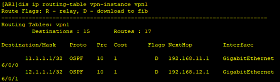
(在AR1查看VPN实例vpn1路由表)
[AR1]dis ip routing-table vpn-instance vpn1
#(通往site1的ospf路由正常,说明site1 mpls vpn配置成功。)
7、site 2 mpls vpn配置
AR4
#sysname AR4
#在AR4上创建VPN实例1
ip vpn-instance 1
ipv4-family
route-distinguisher 100:1
vpn-target 100:1 export-extcommunity
vpn-target 100:1 import-extcommunity
#配置LSR-ID 开启MPLS
mpls lsr-id 4.4.4.4
mpls
#开启MPLS LDP
mpls ldp
#
isis 10
network-entity 49.0000.0000.0004.00
#通往site2的AR5的方向接口GE0/0/0上绑定VPN实例1 并配置IP地址
interface GigabitEthernet0/0/0
ip binding vpn-instance 1
ip address 10.1.1.4 255.255.255.0
#通往AR2的方向接口GE0/0/1的端口配置IP地址
interface GigabitEthernet0/0/1
ip address 24.0.0.4 255.255.255.0
isis enable 10
mpls
mpls ldp
#通往AR3的方向接口GE0/0/2的端口配置IP地址
interface GigabitEthernet0/0/2
ip address 34.0.0.4 255.255.255.0
isis enable 10
mpls
mpls ldp
#配置LOOpBack0 并配置IP
interface LoopBack0
ip address 4.4.4.4 255.255.255.255
isis enable 10
#配置BGP相关配置
bgp 65000
peer 1.1.1.1 as-number 65000
peer 1.1.1.1 connect-interface LoopBack0
#
ipv4-family unicast
undo synchronization
peer 1.1.1.1 enable
#
ipv4-family vpnv4
policy vpn-target
peer 1.1.1.1 enable
peer 1.1.1.1 next-hop-local
#绑定VPN实例1
ipv4-family vpn-instance 1
peer 10.1.1.5 as-number 65001
8、骨干区域 mpls vpn配置
MPLS VPN网络架构由三部分组成:CE(Customer Edge)、PE(Provider Edge)和P(Provider),其中PE和P是运营商设备,CE是MPLS VPN用户设备。
骨干区域<AR1>主要代码组成
配置VPN实例1,并绑定接口,配置IP地址
#
ip vpn-instance 1
ipv4-family
route-distinguisher 100:1
vpn-target 1:1 export-extcommunity
vpn-target 1:1 import-extcommunity
mpls全局开启
#
mpls lsr-id 1.1.1.1
mpls
#
mpls ldp
#配置isis骨干网协议,搭建底层网络
is-level level-2
network-entity 49.0000.0000.0001.00
import-route ospf 1
#
#接口上配置IP地址,开启isis进程号是10并开启动态表签lpd
interface GigabitEthernet0/0/0
ip address 12.0.0.1 255.255.255.0
isis enable 10
mpls
mpls ldp
#接口上配置IP地址,开启isis进程号是10并开启动态表签lpd
interface GigabitEthernet0/0/1
ip address 13.0.0.1 255.255.255.0
isis enable 10
mpls
mpls ldp
#
#接口上配置IP地址,vpn实例配置成1
interface GigabitEthernet6/0/0
ip binding vpn-instance 1
ip address 192.168.11.2 255.255.255.0
#接口上配置IP地址,vpn实例配置成1
interface GigabitEthernet6/0/1
ip binding vpn-instance 1
ip address 192.168.12.2 255.255.255.0
#
bfd 1绑定对等ip 192.168.11.1 vpn实例1接口6/0/0 自动
#
bfd 1 bind peer-ip 192.168.11.1 vpn-instance 1 interface GigabitEthernet6/0/0 so
urce-ip 192.168.11.2 auto
Commit
bfd 1绑定对等ip 192.168.11.1 vpn实例1接口6/0/0 自动
#
bfd 2 bind peer-ip 192.168.12.1 vpn-instance 1 interface GigabitEthernet6/0/1 so
urce-ip 192.168.11.2 auto
commit
#
bgp配置区域为65000,用环回配置邻居对等体
#
bgp 65000
peer 2.2.2.2 as-number 65000
peer 2.2.2.2 connect-interface LoopBack0
peer 3.3.3.3 as-number 65000
peer 3.3.3.3 connect-interface LoopBack0
peer 4.4.4.4 as-number 65000
peer 4.4.4.4 connect-interface LoopBack0
#
ipv4-family unicast
undo synchronization
peer 2.2.2.2 enable
peer 3.3.3.3 enable
peer 4.4.4.4 enable
#
ipv4-family vpnv4
policy vpn-target
peer 4.4.4.4 enable
peer 4.4.4.4 next-hop-local
#
ipv4-family vpn-instance 1
import-route ospf 10
ospf 10,配置 vpn实例1
#
ospf 10 router-id 1.1.1.1 vpn-instance 1
default-route-advertise
import-route bgp
area 0.0.0.0
network 192.168.11.0 0.0.0.255
network 192.168.12.0 0.0.0.255
#
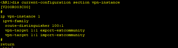
用dis ip vpn-instance in命令,查看vpn实例配置
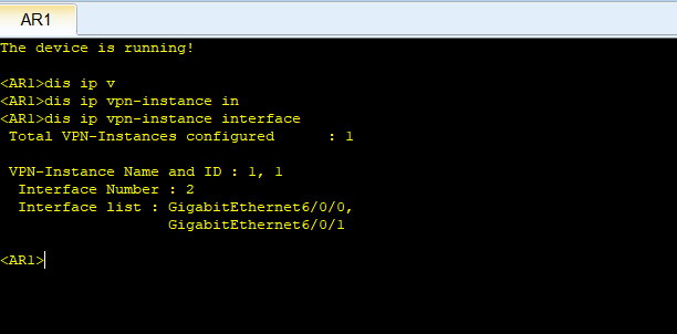
检查vpn实例配置结果
<AR2>主要配置
#
mpls lsr-id 2.2.2.2
mpls
#
mpls ldp
#
isis 10
is-level level-2
network-entity 49.0000.0000.0002.00
#
interface GigabitEthernet0/0/0
ip address 12.0.0.2 255.255.255.0
isis enable 10
mpls
mpls ldp
#
interface GigabitEthernet0/0/1
ip address 24.0.0.2 255.255.255.0
isis enable 10
mpls
mpls ldp
#
bgp 65000
peer 1.1.1.1 as-number 65000
peer 1.1.1.1 connect-interface LoopBack0
peer 3.3.3.3 as-number 65000
peer 3.3.3.3 connect-interface LoopBack0
peer 4.4.4.4 as-number 65000
peer 4.4.4.4 connect-interface LoopBack0
#
ipv4-family unicast
undo synchronization
peer 1.1.1.1 enable
peer 1.1.1.1 reflect-client
peer 3.3.3.3 enable
peer 4.4.4.4 enable
peer 4.4.4.4 reflect-client
#
interface LoopBack0
ip address 2.2.2.2 255.255.255.255
isis enable 10
<AR3>主要配置
mpls lsr-id 3.3.3.3
mpls
#
mpls ldp
#
isis 10
is-level level-2
network-entity 49.0000.0000.0003.00
#
interface GigabitEthernet0/0/0
ip address 13.0.0.2 255.255.255.0
isis enable 10
mpls
mpls ldp
#
interface GigabitEthernet0/0/1
ip address 34.0.0.2 255.255.255.0
isis enable 10
mpls
mpls ldp
#
bgp 65000
peer 1.1.1.1 as-number 65000
peer 1.1.1.1 connect-interface LoopBack0
peer 2.2.2.2 as-number 65000
peer 2.2.2.2 connect-interface LoopBack0
peer 4.4.4.4 as-number 65000
peer 4.4.4.4 connect-interface LoopBack0
#
ipv4-family unicast
undo synchronization
peer 1.1.1.1 enable
peer 1.1.1.1 reflect-client
peer 2.2.2.2 enable
peer 4.4.4.4 enable
peer 4.4.4.4 reflect-client
#
interface LoopBack0
ip address 3.3.3.3 255.255.255.255
isis enable 10
骨干区域<AR4>主要代码组成
ip vpn-instance 1
ipv4-family
route-distinguisher 1:1
vpn-target 1:1 export-extcommunity
vpn-target 1:1 import-extcommunity
#
mpls lsr-id 4.4.4.4
mpls
#
mpls ldp
#
isis 10
is-level level-2
network-entity 49.0000.0000.0004.00
#
interface GigabitEthernet0/0/0
ip binding vpn-instance 1
ip address 10.1.1.1 255.255.255.0
#
interface GigabitEthernet0/0/1
ip address 24.0.0.1 255.255.255.0
isis enable 10
mpls
mpls ldp
#
interface GigabitEthernet0/0/2
ip address 34.0.0.1 255.255.255.0
isis enable 10
mpls
mpls ldp
#
interface LoopBack0
ip address 4.4.4.4 255.255.255.255
isis enable 10
#
#
bgp 65000
peer 1.1.1.1 as-number 65000
peer 1.1.1.1 connect-interface LoopBack0
peer 2.2.2.2 as-number 65000
peer 2.2.2.2 connect-interface LoopBack0
peer 3.3.3.3 as-number 65000
peer 3.3.3.3 connect-interface LoopBack0
#
ipv4-family unicast
undo synchronization
undo peer 1.1.1.1 enable
peer 2.2.2.2 enable
peer 3.3.3.3 enable
#
ipv4-family vpnv4
policy vpn-target
peer 1.1.1.1 enable
peer 1.1.1.1 next-hop-local
#
ipv4-family vpn-instance 1
peer 10.1.1.2 as-number 65001
#
ipv4-family vpn-instance 1
peer 10.1.1.2 as-number 65001
验证
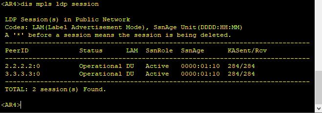
9业务测试
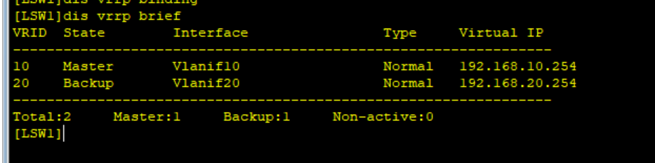
VRRP测试
此为交换机LSW1的vrrp检测在图中LSW1作为vlan10的主vlan20为备
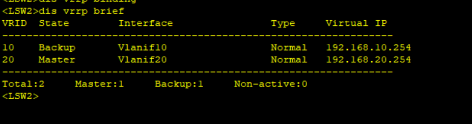
在LSW2中vlan20为主vlan10为备
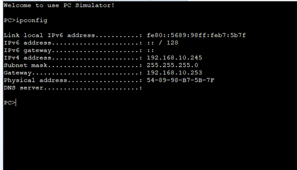
DHCP测试
vlan10的DHCP下发保证PC能获得到IP地址
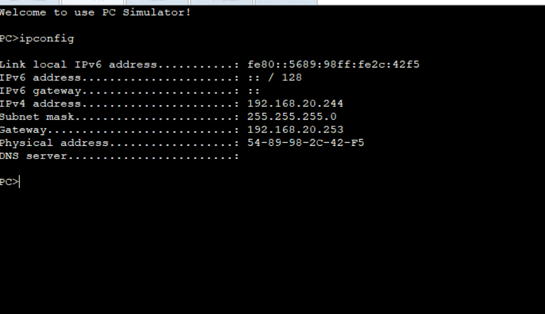
vlan20的DHCP下发
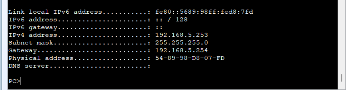
站点2的vlan5下发
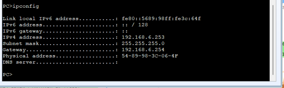
站点2的vlan6下发
bfd测试
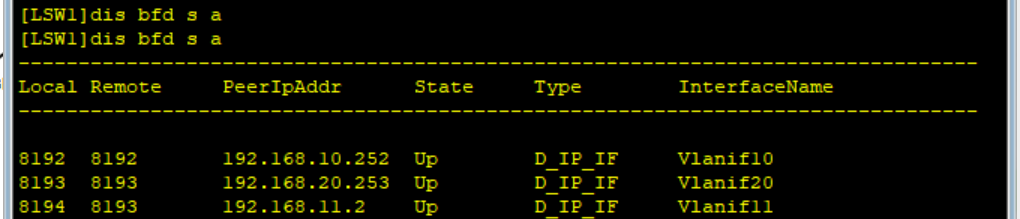
LSW1查看与AR1的bfd接口是否up查看接口已UP
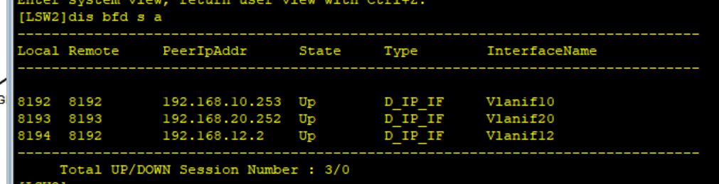
LSW2的查看
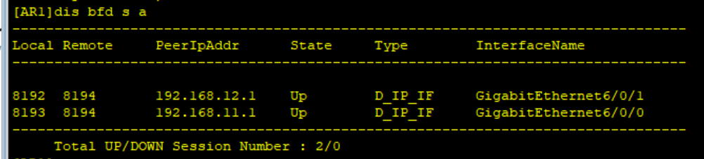
AR1与LSW1和LSW2的bfd接口也up
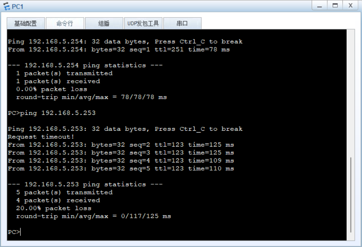
业务联通性测试
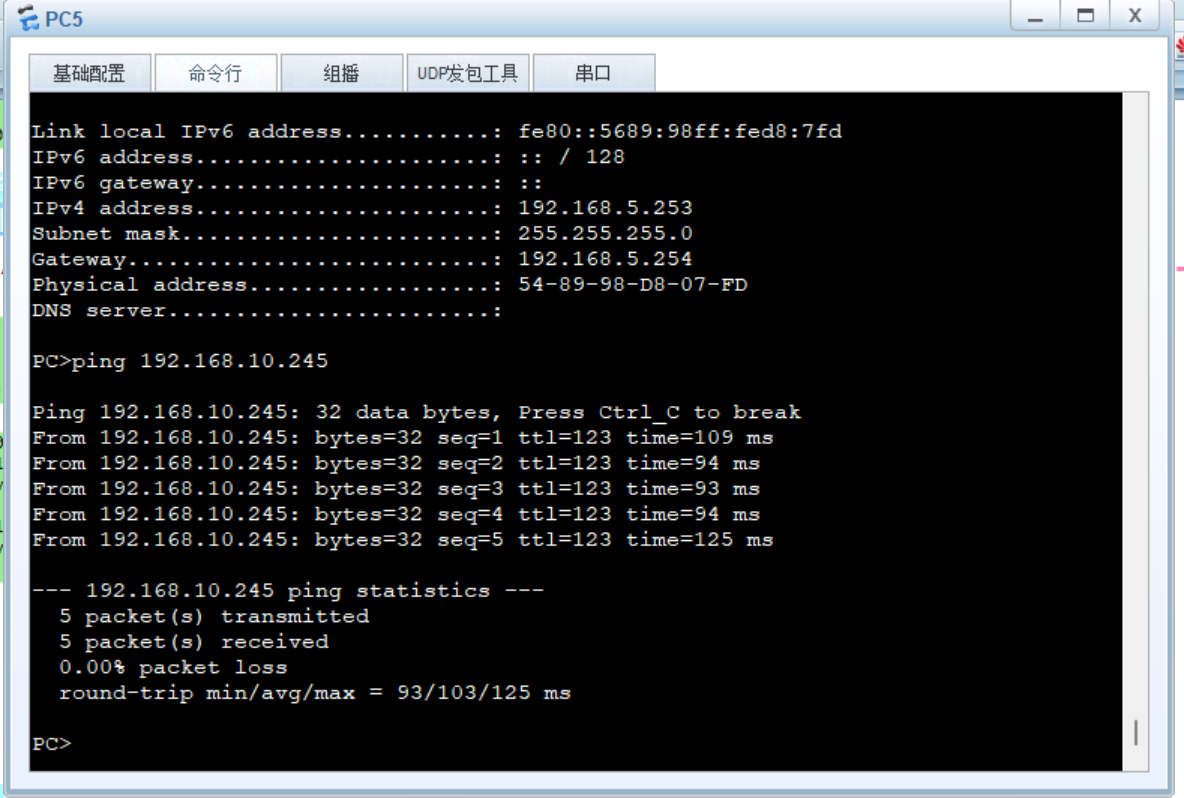
查看站点1的PC1可以ping通到站点2的PC5
PC2中可以查看
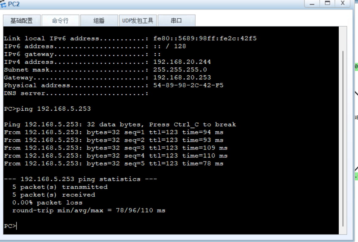
测试站点2能否ping通站点1
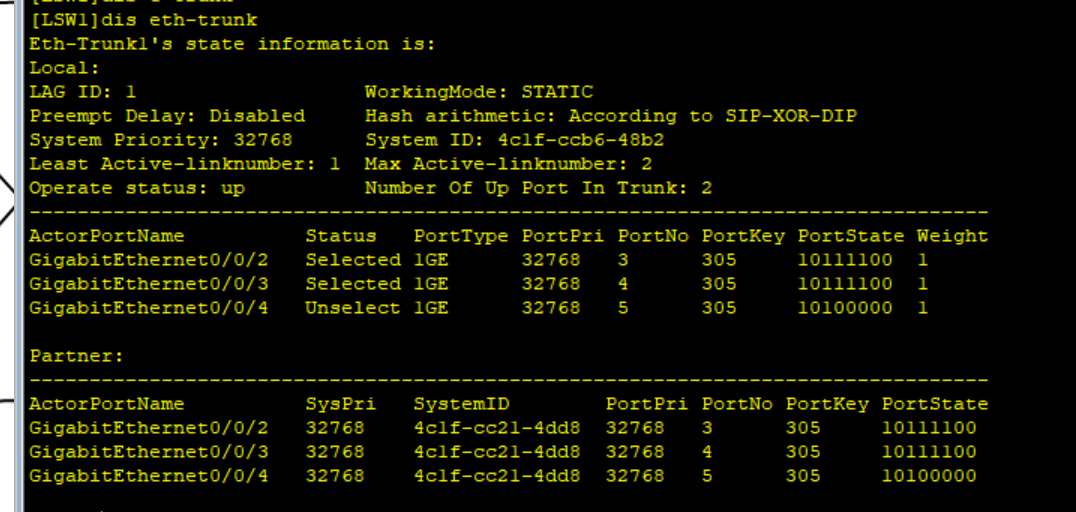
链路聚合查看
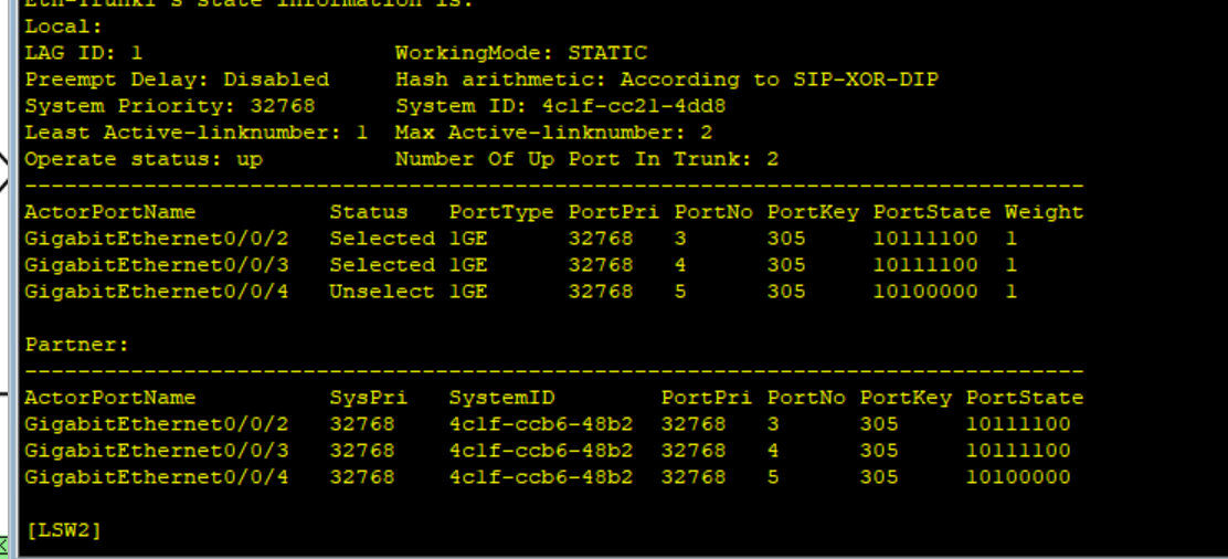
LSW1和LSW2的链路聚合状态
LSW2和LSW1的链路聚合状态
ACL测试
因需求站点1无法和站点2的PC6进行通信需要部署ACL
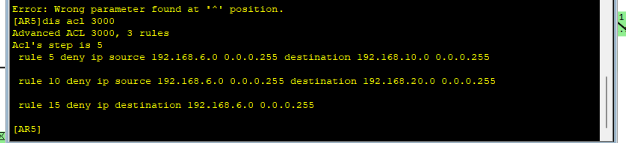
查看是否生效
PC1无法与PC6进行通信
查看PC3无法与PC6进行通信
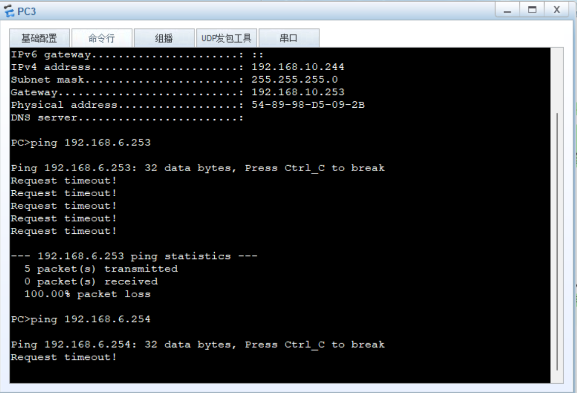
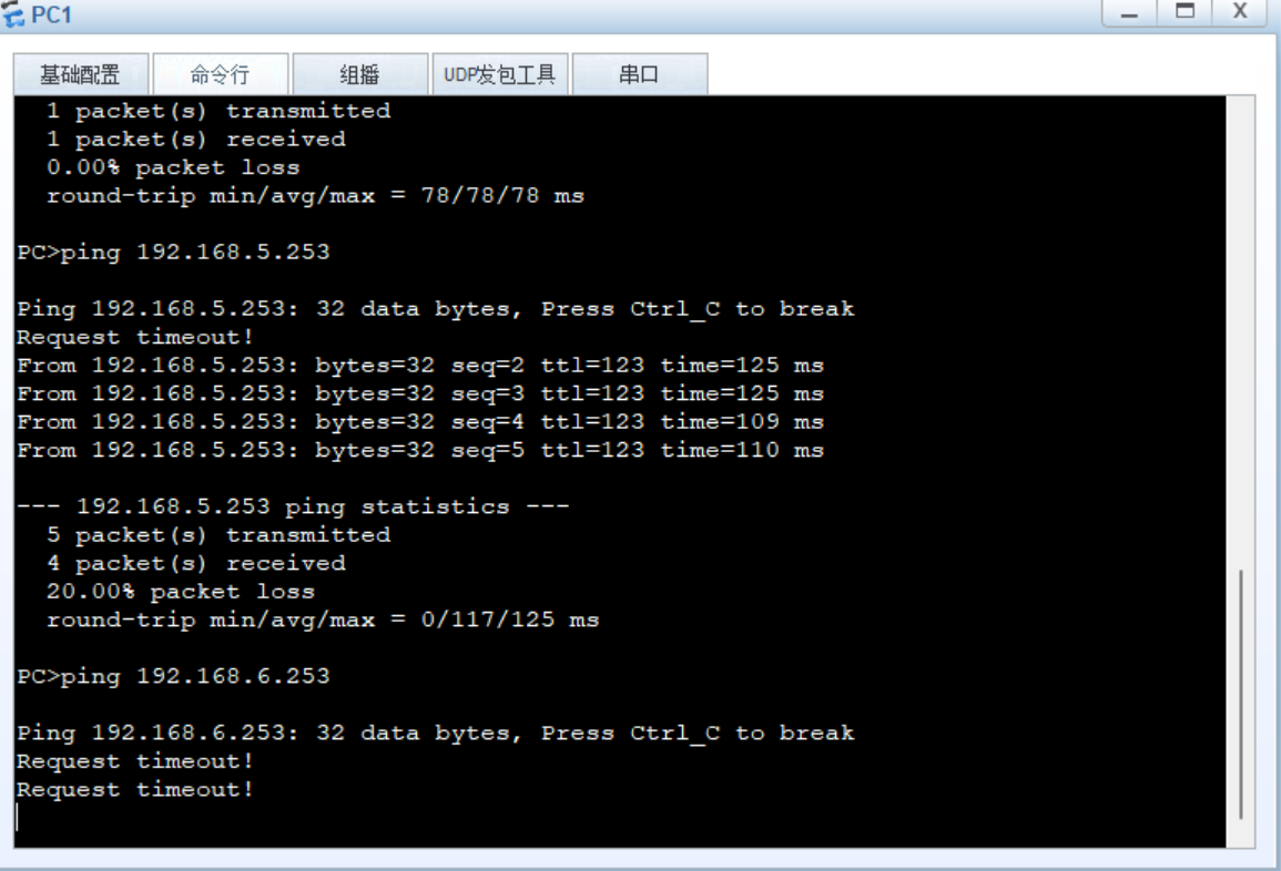
策略生效成功
10切换测试
保证网络可靠性查看
此时用PC1与对方站点进行路由追踪可以发现当前的路径为LSW1与AR1的接口进行通信
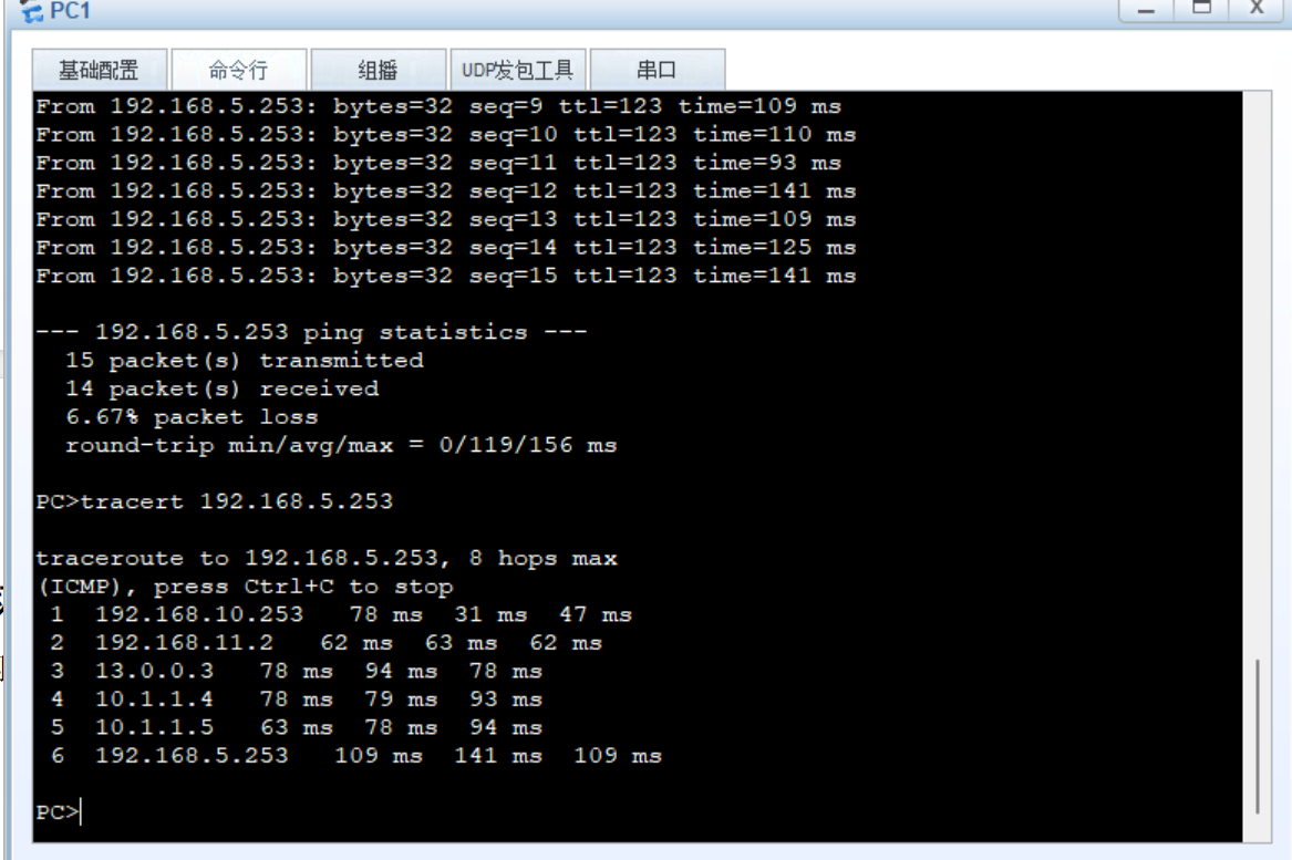
接下来模拟LSW1与AR1的接口断掉看看能不能快速切换

bfd检测到该链路已经down把流量切换到LSW2的出接口进行发送
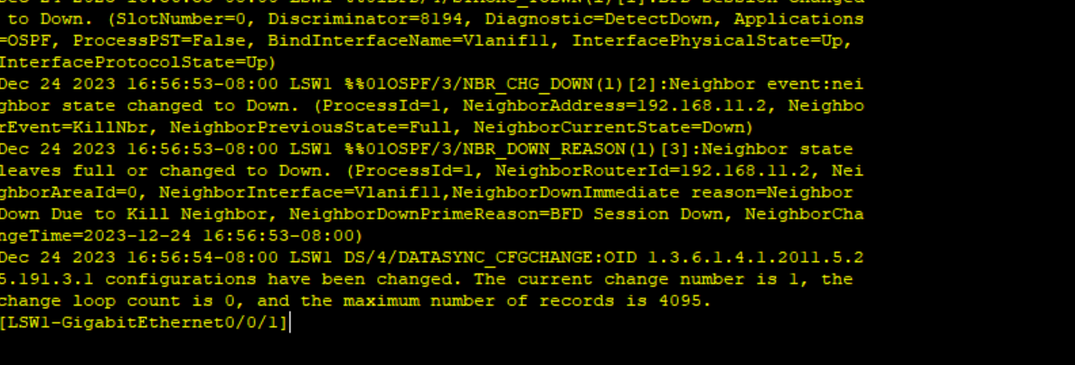
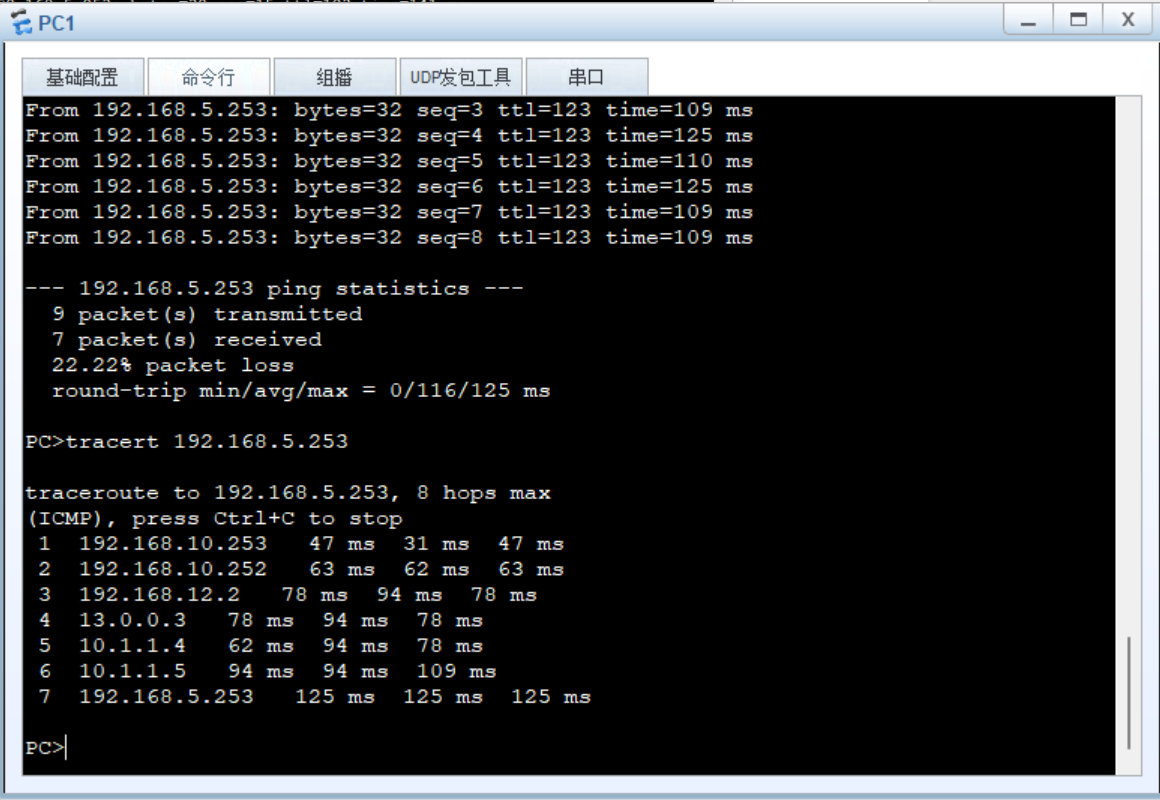
切换成功
模拟vrrp的切换
模拟LSW1故障让流量切换都LSW2到达站点2
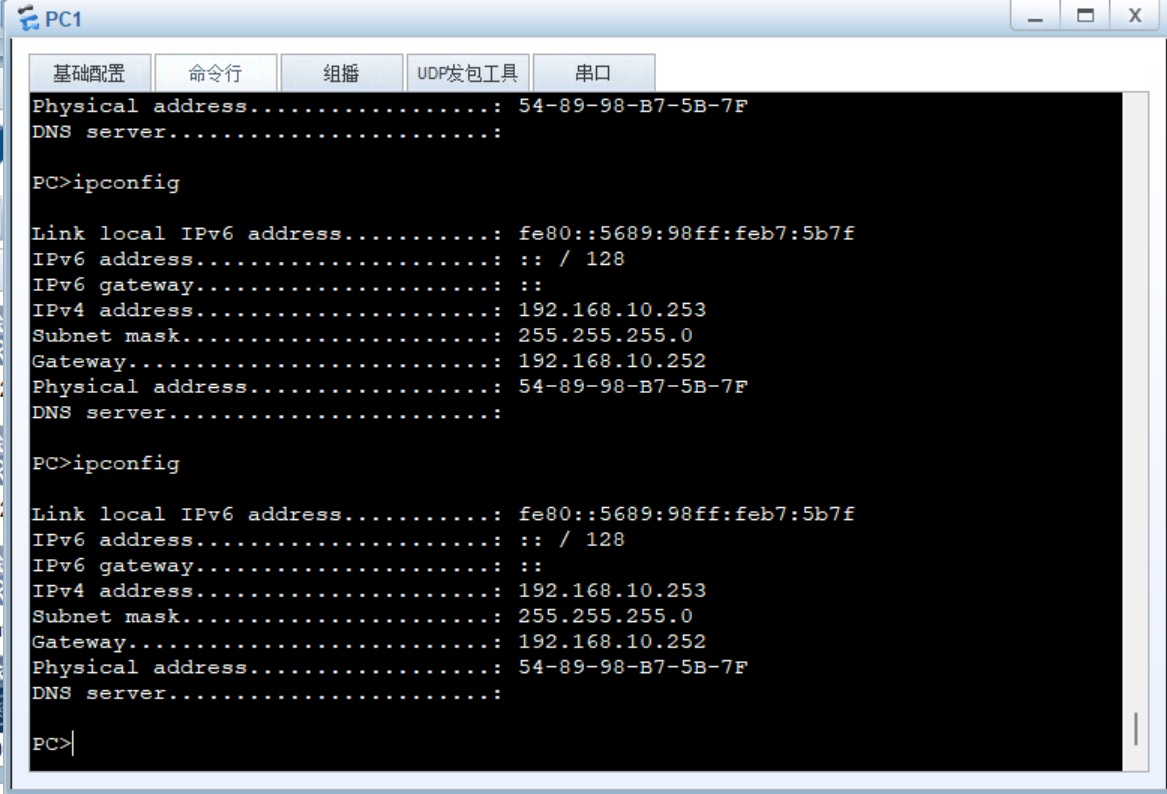
查看当前PC1的网关地址是否是LSW1
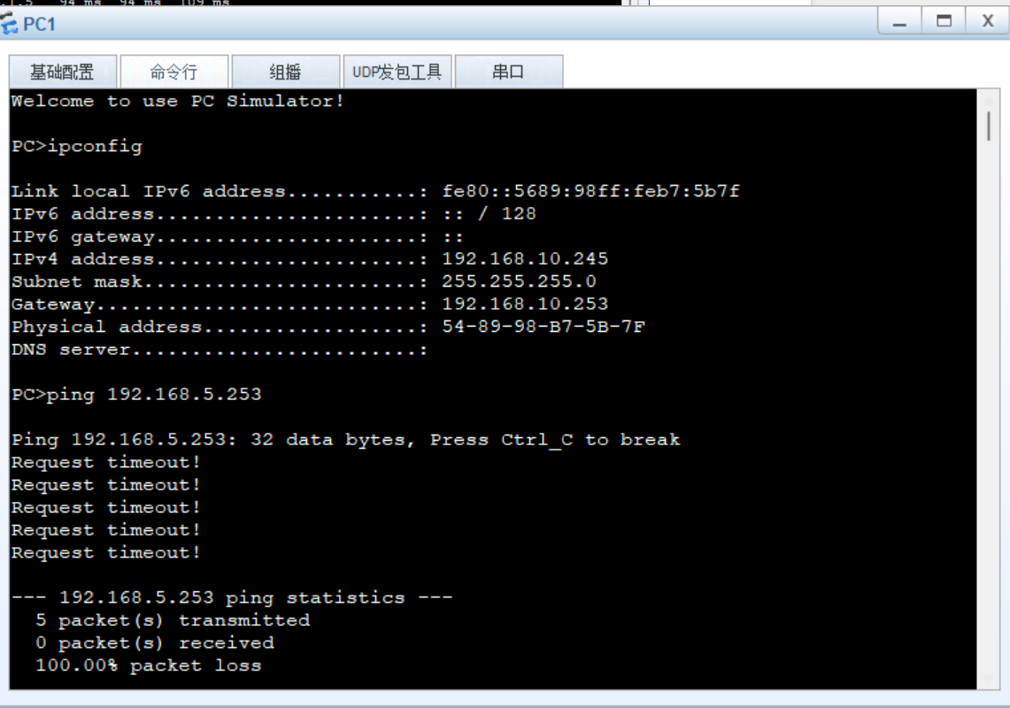
在交换机1进行重启
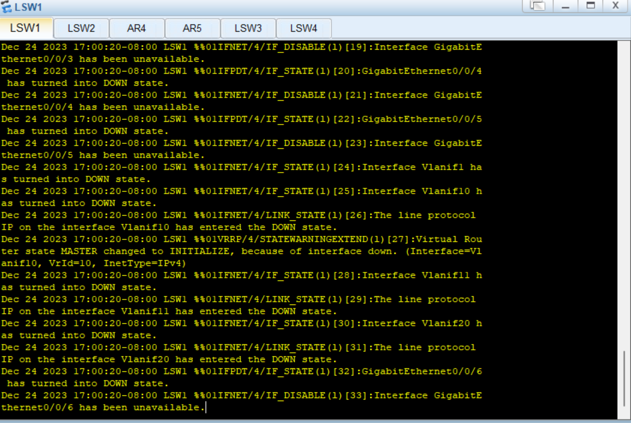
检查PC1的网关已经变成了LSW2
在与PC5进行一次路由追踪查看是否路径已经改变
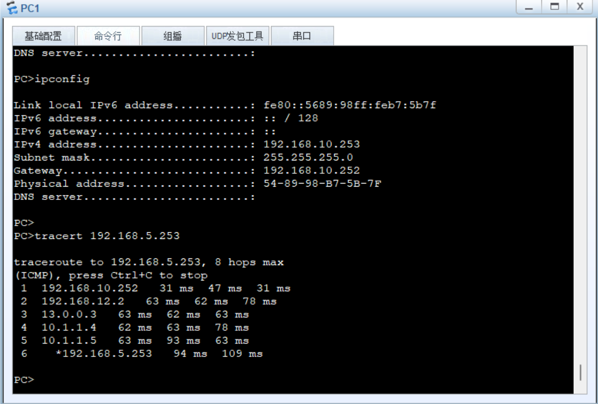
查看已经切换成功冗余路径启用实验完成

